Manual: WiFi Water Level S1


WiFi Water Level S1 Parts
The Control Unit is placed on the outside of the water tank.


Use any from HCSR04 sensors family, that can work with 3.3V
AJ-SR04M (recommended)

RCWL-1670 (could require special case and waterproof treatment)

Installation And Usage Guide


Ensure that good 2.4GHz WiFi signal will reach the device area all the time.
Optimal Wi-Fi signal strength is crucial for device performance. Before installation, use a mobile app (WiFi Analyzer) with a 3dBm reference antenna to measure the signal at the location. Ensure it's between -30 dBm and -78 dBm. After connecting, regularly verify this on the device's webpage.
If WiFi signal strength is weak consider add WiFi range extenders.
Input Power Options:
-
In locations receiving direct sunlight for at least 3 hours per day, the solar panel lid can be utilized.
- Completely wireless and capable of operating autonomously through solar power, provided the area receives sufficient sunlight.
- Designed and tested for outdoor use, resistant to rain, sunlight, and typical outdoor weather conditions.
- Powered by 3 AA NiMH rechargeable batteries, the device offers easy maintenance and provides backup power during periods of low sunlight.
- Ensure use good brand and quality AA NiMH batteries, 2000 mA or more.
- Only use AA NiMH rechargeable batteries.
- To prevent damage to the device, please remove batteries if they are depleted, damaged, or if the device will be stored for an extended period without exposure to sunlight.
-
When using solar power as the input, ensure the USB-C port is sealed to
prevent damage from rain or moisture. Use the provided USB-C cap and optionally
seal it with silicone for added protection.

-
To operate in indoor environments or areas with limited sunlight, simply connect the device to a power source using the USB-C port.
Note: When using the USB-C port for power, please ensure that batteries are removed to prevent damage to the device.
Note: Using the AC/DC power adapter outdoors or near water requires special safety precautions. Consult a qualified electrician if necessary. Ensure all cables are properly insulated to protect them from water and unpredictable weather conditions.
-
Depending on the water level measurement frequency configured for the device, it could consume up to 70 mA for approximately 6 seconds at 3.3V, each cycle.
-
Power Selection: To select your preferred power source (Solar, USB-C), locate the Power Selector switch on the device. Toggle the switch to the desired setting.
In this step, configure the device to connect to your local internet WiFi network
This will allow you to link the device to your profile and personalize your settings.
Steps:
- 1) Connect the device to a power source. Ensure WiFi antenna is connected at Control Unit.
-
2) Using a cellphone, search and connect to a 2.4GHz WiFi network named WaterLevelProSetup with credentials/password: 1122334455
If the network name doesn't show or disappears quickly, check USBC power input or press the WiFi Reset button at Control Unit.To reset the Wi-Fi, power on the device using either the USBC cable or solar power. Immediately after powering on, quickly press the Wi-Fi Reset button 2-3 times.
-
3) Enter your local WiFi auth info.
After completing step 2), a Captive Portal will appear on your cellphone. This will guide you to a webpage where you can select the desired Wi-Fi network and enter its credentials. You will also be prompted to enter an email address to link the device to your existing account.
If the Captive Portal don't load automatically use this url http://192.168.4.1/ to load it manually from cellphone.
-
4) Check your device is online
Reconnect your cellphone to the internet and log in to your account. If everything was successful, you will see the new device listed in your account with an "Online" status.
If the device does not show online, try reconnecting the power source or repeating the entire process after pressing the Wi-Fi Reset button on the device.
-
Place the device sensor as far as possible from the main water inlet of the water tank, without reaching to much closer to the water tank internal wall, to avoid erroneous measurements when filling the water tank.


-
Keep in mind that the internal sensor that is placed inside the water tank must have a minimum margin of 20 centimeters (AJ-SR04M Sensor) from its bottom location to the maximum distance that the water in the tank can reach.

If the tank cannot preserve that minimum distance margin, the sensor blind area is reached and erroneous random measurements will be reported. Use the RCWL-1670 Sensor if require smaller blind area (2 CM).
The installation location may vary depending on the shape of your water tank, how the lid closes, and its resistance to local conditions. Please choose an installation method that ensures the device is securely mounted and protected. As this is an experimental device, the user is responsible for ensuring proper and safe installation.
-
Placement of the upper Control Unit.
The control unit can be installed using two main methods, depending on your specific setup and preferences. Please ensure that the chosen method provides a secure and stable mounting for optimal performance.
Screw Mounting Method:
- Locate the designated mounting points on the control unit.
- Use appropriate screws to securely fasten the unit to a flat surface, such as a wall or a sturdy panel near the water tank.
- Ensure the screws are tight and the unit is firmly fixed to avoid movement or detachment over time.
Pipe Mounting Method:
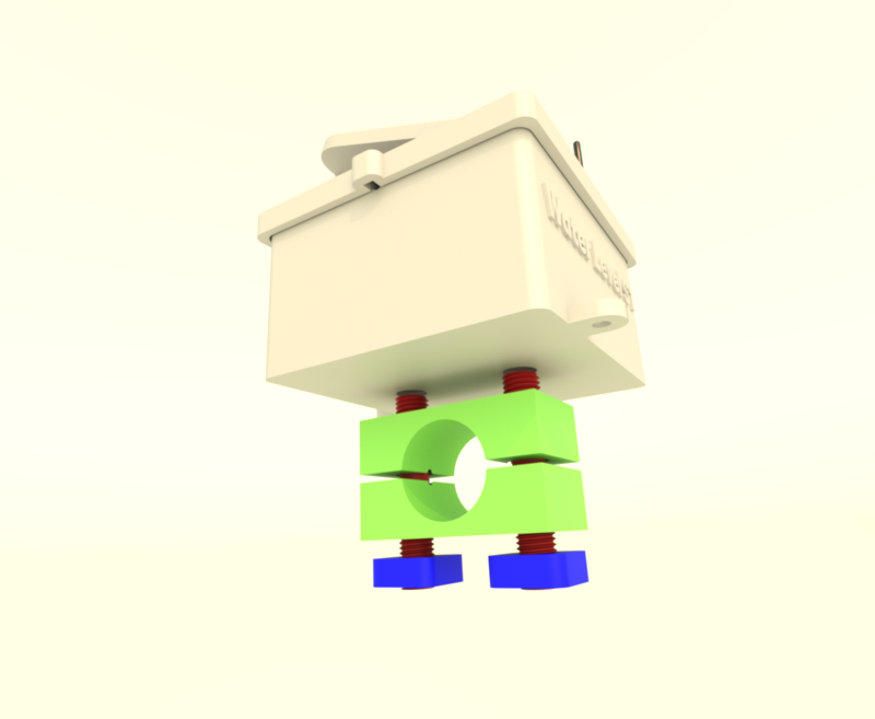
-
This method is ideal for installations over a pipe or cylindrical structure with a diameter of approximately 27mm.
- Use the screws, nuts, and mounting accessories provided with the model to securely attach the control unit to a pipe of approximately 27mm in diameter.
- Ensure the unit is tightly secured and aligned properly to prevent shifting or tilting during operation.
- For the pipe mounting option, inspect the quality of the 3D-printed screws, as they may break depending on the print quality, material, or other factors.
Regardless of the installation method, always verify that the control unit is mounted in a location that is safe, stable, and well-protected from adverse environmental conditions.
-
Positioning the Control Unit for Solar Power
If you are using solar power to operate the control unit, it is crucial to position the device to maximize its exposure to sunlight. Follow these guidelines for optimal solar performance:
- Orientation: Ensure the solar panel is facing the direction that receives the most sunlight during the day. In most regions, this means orienting the panel toward the south in the northern hemisphere or toward the north in the southern hemisphere.
- Avoid Obstructions: Place the control unit in an area free from shadows caused by trees, buildings, or other objects that could block sunlight during the day.
- Regular Maintenance: Clean the solar panel periodically with mild soap and water, avoiding alcohol or harsh chemicals. Use a soft cloth and rinse thoroughly to remove any soap residue, ensuring the panel stays efficient and protected.
-
Mount the AJ-SR04M Internal Sensor
- Drill a 12mm hole in the tank lid, far from the water inlet and wall.
-
Thread the sensor cable through, pointing the sensor toward the water.
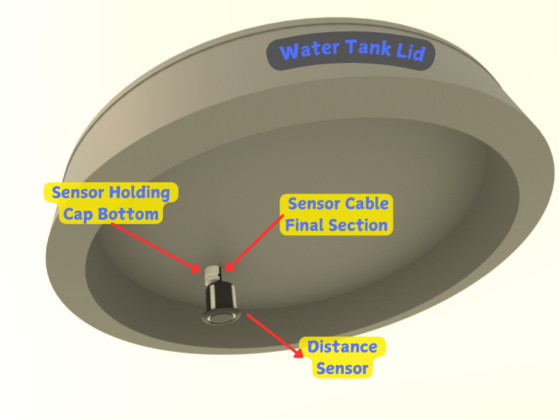
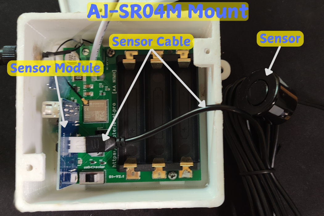
-
Open the S1 lid and connect the sensor cable to the module inside.
- Close the lid, sealing it to prevent moisture, ensuring proper cable exit.
-
Attach the sensor with the supplied mounting cap, tightening it near the top of
the tank. If needed, enlarge the hole and use silicone for a better seal.
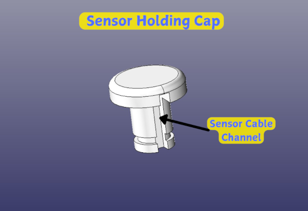
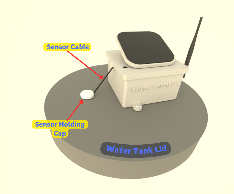
- Secure the remaining sensor cable to prevent movement and damage.
To accurately measure the water level in the tank, you need to set the device to recognize the point where the tank is considered empty. In summary, this ensures the device calculates the tank's total capacity correctly.
-
1) Log in
Log in to your account account using the same email address provided during the device's Wi-Fi setup. Ensure both emails match for proper account synchronization.
-
2) Update the "Empty Level" in Settings
After logging in, find your new device in the "My Devices" list. Open the device's details page and click the "Device Settings" button at the bottom.
In the settings, adjust the "Empty Level" by entering the distance (in centimeters) from the internal sensor to the bottom of the tank, representing the point at which you consider the tank to be empty.
-
3) Update the "Top Margin" in Settings
The Top Margin property specifies the unused space at the top of the water tank. Typically, tanks have at least 20 cm of empty space at the top to prevent overflows, controlled by a float valve or similar mechanism. Setting this value ensures more accurate readings, indicating when the tank is truly at 100% capacity.
In the settings, adjust the Top Margin to define the distance (in centimeters) from the sensor to the maximum water level. This ensures the system accounts for the unused space at the top of the tank, providing more accurate measurements of full capacity.
- AJ-SR04M: The AJ-SR04M sensor has a blind area of 20 cm, meaning it cannot measure distances within this range. To ensure accurate readings, a Top Margin of at least 20 cm is required.
- RCWL-1670: The RCWL-1670 sensor has a blind area of 2 cm, meaning it cannot measure accurately within this range. To ensure proper functionality, set a Top Margin of at least 2 cm.
Depending on the sensor model, it may have a blind spot where it cannot detect accurately. If the water level enters this blind area, the sensor might report random or unreliable measurements.
-
4) Update "Liters per cm" in Settings
Set Liters per cm to convert each centimeter of water height into liters. This helps the app show volume changes more accurately.
Quick estimate: Liters per cm = usable tank liters / usable tank height in cm. Start with this value and fine-tune after a few real fill/drain cycles.
Open Source & Open Hardware
This project is fully open-source and open-hardware. You can access the source code and hardware design files through the following links:


This open-source electronics project/device is provided strictly for experimental, educational, and developmental purposes. It is offered "as is," without any warranties, express or implied. This includes, but is not limited to, implied warranties of merchantability, fitness for a particular purpose, or non-infringement.
By using this device, you acknowledge and accept that:
- You assume all risks associated with its use, including but not limited to potential damage to property, personal injury, or any other unintended consequences.
- This device is not certified for commercial, industrial, or safety-critical applications. It is intended solely for developers, hobbyists, and other users with appropriate technical expertise.
- The creators and distributors of this project are not liable for any damages, losses, or inconveniences resulting from its use, modification, or integration into other systems.
Users are solely responsible for ensuring that the use of this device complies with local laws, regulations, and safety standards in their region.
S1 Device Subscriptions
-
Basic free plan to use the device without costs.
Minimum frequency updates 120 seconds. -
Buy this monthly subscription to enable faster frequency updates up to 30 seconds. 1-Week Free Trial
Minimum frequency updates 30 seconds.